Dry-spinning
method is extensively employed in fiber industry, comparing to the
counter-part of wet-spinning process, it has advantages of
environmentally friendly, high yield rate and no need for purification.
Here, we report the synthesis of graphene oxide (GO) fibers via dry
spinning GO inks with extremely high concentrations. The proper rheology
properties of such GO inks allow us to dry spin GO fiber directly.
Various dry spinning conditions are investigated, and the relationship
between mechanical performance and micro-structure of the obtained GO
fiber are established. We found that the existence of larger GO liquid
crystal domains does not necessarily result to higher mechanical
properties, and it is because those large GO liquid crystal domains
evolve into thick GO films during drying process and thus prevent the
intimate compaction of the whole GOF and leave behind gaps. This is
detrimental for the mechanical properties, and thus the dry spin GOF are
much weaker than that of wet spin ones. Importantly, Barus effects,
that generally arise during the melt spinning of polymers, were not
observed, indicating that caution must be taken when classical polymer
rheology theories are applied to investigate the dynamic behaviors of GO
solution.
Introduction
Graphene has super mechanical, electrical and thermal properties, due to its sp2 carbon based crystal structures1,2,3.
The assembly of graphene into graphene based macro-sized objects (GMO)
that can inherit some outstanding characteristics of graphene is
extremely important for the practical application of graphene. In the
past several years, there has indeed witnessed significant advancement4,5,6,7,8,9,10.
For example, Ruoff’s group firstly reported graphene oxide (GO) paper,
in which graphene nanosheets are stacked tightly layer-by-layer, and
these GO papers exhibited high strength and modulus4. Graphene aerogel/hydrogel is another typical GMO. Shi et al.
employed hydrothermal method to synthesize graphene hydrogel, and such
GMP possesses high electrical conductivity, porosity and accessible
surface area, and thus provides competitive candidate for the electrodes
in energy storage materials. Cheng and Ren creatively replaced the
original 2-D metal catalyst foil by 3D porous one to grow graphene foam,
which significantly push and trigger the research in this area10. All the above development manifests the versatility and great potential for GMOs.
Among
all GMOs, graphene fiber (GF) is very interesting and attractive, since
it is strong, lightweight, flexible and conductive, based on which a
large amount of new applications might be envisioned11,12,13,14,15.
Wet spinning method is a quite general strategy to prepare fibers, and
in principle, any nanoparticle dispersion can be gelled into fiber when
the right combination of dispersion agent and coagulation solution are
employed16,17. Gao et al.
took the advantage of spontaneously developed liquid crystal behaviors
of GO with relatively high concentration, successfully developed a
series of high performance GFs by wet-spinning18. Wallace et al. further employed DNA to wet spin synthesized GFs, aiming for the GFs based tissue engineering19. Interestingly, Qu et al. expanded the hydrothermal process to the synthesis of GFs, by using hollow glass tube as autoclave20.
Very recently, Chen further advanced this strategy by replacing the
hollow glass tube by flexible silica hollow tube, which significantly
improved the GF yield21. The obtained graphene hybrid fibers showed excellent energy storage performance.
However,
it worth to be pointed out here, that almost all the reported GFs are
synthesized either by hydrothermal or wet-spin. Fiber spinning is
actually a method that has been extensively used since several decades
ago in textile industry, and various spinning strategies have been
tested and optimized. Wet spin and dry spin are the two most used
spinning method22,23,24.
Comparing wet spinning method, the productivity of dry spin is much
higher, and even more importantly, purification is not necessary22.
Unfortunately, for the best of our knowledges, the studies of the dry
spinning GFs are still very limited. When this paper is still under
review, Gao’s group firstly reported dry spinning GFs25.
Even though extruding high concentrated GO gel has been announced by
other groups in their investigation of 3D printing graphene structures26,27,
the rheological properties of GO, as well as its physical impact on the
drying dynamics, micro-structures and mechanical properties of the
prepared fibers still need to be clarified. In addition, the highly
hydrophilic characteristics of GO limited the maximum concentration of
GO solution we can achieve, the GO fibers immediately obtained by
wet/dry spin still contain a large amount of water. This makes the
drying process, during which GO sheets are assembled into closely packed
structure, become the key step in order to control and modify the
performance of the final GO fibers. Keeping the above considering in
mind, we focused, in this study, on the dry spinnability of GO inks, and
relationship between spinning conditions, including rheology properties
of GO and size of spinneret, and GF mechanical properties, are
established. A model for the development of microstructure during drying
process of gel GOFs was also provided.
Results and Discussion
The
rate of GF synthesis by our dry spin method is very high, which is
mainly determined by the spin rate. This is because comparing with wet
spin, there is no need for extra treatment, such as purification, for
dry spin GO fibers, which not only time consuming, but also involve
chemical solvent that make potential pollution. This advantage of dry
spin makes it very competitive. On the other hand, considering the GO
concentration of the dry spin ink is significantly higher than that in
wet spin, the behaviors of GO assembly during the spinning and drying
process, as well as the micro-structure of obtained solid GO fibers
could be very different. The evolvement of liquid crystal distribution
as the GO ink concentration increased can be seen in Fig. S1.
As the GO concentration increased from 0.5 mg/ml to 20 mg/ml, the
average size of liquid crystal domain increased accordingly. However,
when the concentration is as high as >40 mg/ml, the POM signals are
significantly reduced because of the low transmittance of the GO
solution, which prevent the qualitative measurement of the average
crystal liquid size.
The gel GOFs immediately extruded from
spinneret still has a large amount of water (90–95%), however, it can
still perfectly be self-supported with no observable changes of the
shape during spinning process. This is guaranteed by the proper rheology
properties of GO ink as will be elaborated in the following. After the
GOFs were dried by fixing two ends with controlled force, it was
observed that, all GFs shrink along their axial direction by ~8%, while
the radial direction by ~85%. Such asymmetry shrinkage manifested that
most of liquid crystal domains are aligned in the axial direction, which
is induced by the shear stress generated by the spinneret during the
spinning process. Because of the structure stability of the gel GOFs,
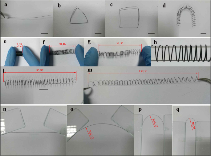
they can form various complex shapes and structures shown in Fig. 1
and video in the supplementary materials. This is very different from
the wet-spin process, in which fibers randomly float in coagulation
solution. Such characteristic allows us to use this technique to pattern
GO fibers on flexible substrate. As prove of concept, GOFs can be
directed extruded on curved substrate, such as a glass bar, to fabricate
a highly compressible spring shaped structure as shown in Fig. 1.
This GO spring can be compressed and stretched between 7.37 mm and
130.33 mm. Considering the high chemical robustness and mechanical
properties of graphene, those springs might be used to replace metal
spring for vibration isolation in some chemical corrosion environment.
The evolvement of microstructure of GOF during drying process was
investigated by freeze-drying the GOF after dried for some time (0 min,
5 min, 10 min, 20 min, 30 min, 40 min) as shown in Fig. S2.
It can be seen that, the GO nanosheets in the peripheral of the
dry-spun GO fiber stacked in parallel, while packed relatively randomly
in the core, thus forming core-shell structures. The thickness of the
shell is mainly limited by the boundary layer. According to the
fundamental fluid mechanics, the boundary layer thickness is roughly
inverse proportional to the viscose of the fluid. Since the GO ink used
for dry spin has very high viscosity, as compared to the case of wet
spin, the boundary layer thickness is much less. This is probably one of
the main reason why the dry spin GO fiber is weaker than the one
obtained by wet spin as we will elaborate in the follows. In addition,
the shell is formed immediately once the GO fiber is extruded out of the
spinneret. This could prevent the further water evaporation and induced
high capillary force, which eventually bend the shell towards the core,
as can be seen in the SEM images.
Figure 1
Morphology and flexibility of graphene fiber. Photographs of (a–d) GOF with various shapes; (e–m) GOF springs can be compressive and stretched to large extend. The scale bar in (a–d) is 5 mm.
There
is a critical difference between the inks for dry spin and wet spin
that should be clarified, in order to elaborate the fundamental
mechanisms for the micro-structure formation during drying process and
related mechanical properties of GO fiber. Since coagulation agents,
such as metal ions, are employed for the formation of gel GO fiber in
wet-spin process, the minimum spinnable concentration of GO can be very
low (less than 2 mg/ml)12,
and thus rheology property of the GO ink is almost irrelevant. In
contrast, for dry-spinning method, proper rheology performance is the
key factor. It is required that once the GO ink is extruded out of the
spinneret, it must have the capability to self-supported. As can be seen
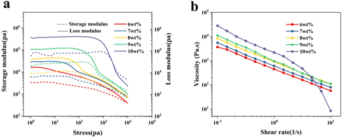
in Fig. 2,
the rheology properties are highly dependent on the GO concentration.
The storage modulus is higher than loss modulus for all the tested GO
concentrations, while their difference become larger with GO
concentration. For the ink with highest concentration of 10 wt%, the
storage and loss modulus are as high as 0.3 MPa and 0.08 MPa,
respectively. On the other hand, the yield stress, corresponding to the
cross-point of storage modulus and loss modulus, gradually decreased
from 9 kPa for ink of 6 wt% to 2 kPa for ink of 10 wt%. This might
indicate that the average domain size of liquid crystal of GO ink
increase with GO concentration, which allow GO nanosheets to align
themselves more easily in a same direction under shear stress. In
addition, shear thinning effects can also be clearly seen for all the
tested inks (Fig. 2(b)). When the shear rate increased from 0.1 to 10 1/s, viscosity decreased significantly by more than two orders of magnitude.
Figure 2
Rheology properties of the GO ink with various concentrations.
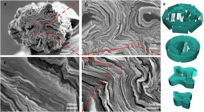
The micro-structures of the GO fibers are shown in Fig. 3.
Interestingly, the cross-section of GOF takes a clear star shape, with
the periphery forming crumples and folds towards the center of the
fiber. Holes and defects due to such folding can be clearly observed,
marked by the boxes in Fig. 3(b).
Such morphologies are explained by analyzing the drying process of GOF
as follows. It has been pointed out by many groups that, GO nanosheets
close to the inner wall of spinneret are subjected to high shear stress,
which align these GO nanosheets to each other and form much more and
larger liquid crystal domains than that far away from the inner wall12.
Therefore, the gel GOF immediately extruded from the spinneret has
“core-shell” structure, with the shell consists of closely packed GO
liquid crystal domains and core of relatively randomly distributed GO
nanosheets or small GO liquid crystal domains (Fig. 3e).
As water evaporated, the concentration of GO increased, the “shell”
region of the gel GOF gradually evolves into water impermeable and
continuous solid GO shells by connecting the original isolated GO liquid
crystal domains. In fact, this is reminiscent of the strategy to
synthesize GO paper at the air-liquid interface as reported by many
groups. The gaps between those continuous GO shells became the only
channels for water evaporation. Upon further drying, the GO shells are
bent severally because of the capillary force, and many folds are
generated as can be seen in Fig. 3,
between which gaps and defects are naturally formed. Note that, because
most of the isolated GO nanosheets are already assembled into shell or
laminate structures, there is very limited number of GO nanosheets, that
is flexible, are available to fill these gaps and defects. Therefore,
the GOFs obtained by dry-spinning only possess relatively low mechanical
properties of fibers, comparing to wet spinning. For the wet-spinning
GO fibers, since the GO concentration for the ink is much lower than
that of dry spinning, GO liquid crystal domains are much smaller and
fewer, and a large number of GO nanosheets are still freely to be
involved into the assembly process, both of which help the close compact
of the whole fiber structure.
Figure 3
SEM images of GOFs (a–d) and schematics illustrating the GO assembly during drying process.
As
the initial study for the dry spinning of GOFs, we mainly focused on
the effects of GO concentration, diameter of spinneret and chemical
reduction conditions on the mechanical and electrical properties of GFs.
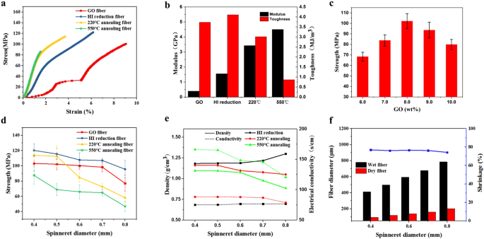
Typical stress-strain curves are showed in Fig. 4(a).
For GOFs, the stress increase with strain with a strengthen stage
between 2% and 3%, followed by a “yield” stage in the strain range of 3%
and 5%. Upon further stretching, a second strengthen stage immerge.
Such evolvement of stress-strain curve is similar to that of the foam
structure with hierarchical architectures, and can be explained by the
micro-structures of GOFs as elaborated above. More specifically, the
defects and gaps formed spontaneously during the drying process can
result to the slippery between different shells under tensile stress.
Due to the Possion’s ratio effect, when the fiber is further stretched
along axial direction, the gaps are closed gradually by compressive
strain in the plane of cross-section, which activates internal static
frictions and thus effectively increase the stiffness of the GOF. This
can explain the observation that Young’s modulus of GOF is increased
when the strain is less than 3%. However, when external stress exceeds
some critical threshold value, graphene shells/laminates start to slip
with each other, corresponding to the “yield” stage between 3% to 5%,
until these graphene shells tightly compact once again and thus
strengthen the whole GOF structures. The fracture strain of GOF is as
high as 9%, and much higher than the counterpart of wet spin GOF12, and is comparable with the ones that scrolled from GO film28. The GOF has an average tensile strength of 105 MPa, Young’s modulus of 0.4 GPa, and fracture toughness of 5 MJ/m3,
which is similar to structural nature materials, such as nacre. Upon
chemical reduction by HI, the Young’s modulus, strength and toughness
are all increased, with the former much more significantly (increased by
~200%). Thermal treatment (at 220 °C) can further enhance the modulus
but not the strength, and also decrease the fracture strain
significantly. “Yield” stage is not observed for the reduced samples.
Indeed, as reported by Pei, there would be significant amount of iodine
laminated between GO layers, which might reinforce the whole structures29.
Therefore, the gaps and defects in GOFs are probably filled at least
partially with the residue iodine, and thus prevent the slippery of GO
shells relative to each other. After annealing at 550 °C for two hours,
at which most of iodine residue is volatilized to gas, the strength even
decreased, and this can be related to the inevitable gas generated
porosity. We microstructure and chemical composition of GOF after
different reduction treatment was also investigated by SEM and XPS,
respectively (Figs S3–4).
It can be seen that, after HI reduction, the structure of GO fiber
became much fluffier, while the core-shell structure is more or less
maintained. The thermal treatment at 220 °C and 550 °C do not change the
morphology significantly, relatively intact shell structure can be
distinguished. Interestingly, based on XPS data, the GO fiber is only
partially reduced, with the extent much less than what we expected. This
is probably because of the dense and parallel packing of GO nanosheets
in the shell of the fiber. As illustrated by Geim’s group, reduced GO
film is impenetrable for all molecules, even Helium30,31.
The shell structure prevents the diffusion of HI agent deep into GO
fibers, and thus greatly limits the reduction of GO. As for the case of
thermal treatment, the reduction process could also be inhibited by such
confinement.
Figure 4
Mechanical and electrical properties. (a)
Typical stress-strain curves for GO fibers (GOFs), HI reduced GO fibers
(H_GF) and thermal treated GO fibers (HT220_GF and HT550_GF); (b) Modulus and toughness; (c) strength dependent on GO concentration; (d) strength of the fibers at before and after reduction; (e) The dependence of electrical conductivity and density on spinneret diameter. (f) Barus effects investigation.
The GO ink concentration and spinneret diameter dependent of the strength were also investigated. Figure 4(c)
shows that the maximum strength is obtained for the fiber with
concentration of 8%. This is probably related to the fact that clogs of
spinneret occur now and then when GO is very high (>8%). Indeed, when
the average domain size of GO liquid crystal is comparable to the
diameter of spinneret, the smooth extrusion of GO ink could be
interrupted (Fig. S1). On the other hand, with increasing the spinneret diameter (Fig. 4(d)),
the strength of all fibers decrease, which is mainly due to the less
alignment of GO that induced by larger spinneret diameter. Figure 4(e)
also shows the dependence of density and electrical conductivity of GFs
on the spinneret diameter. Interestingly, it seems that both the
density and conductivity are insensitive to the spinneret diameter,
except for the HT550_GFs. The conductivities of H_GF, HT220_GF and
HT550_GF are 75, 85 and 112 S/cm, respectively, which is comparable to
the GFs obtained from wet-spin. This should be related to the fact that
most of the iodine residues in fibers can be eliminated by thermal
treatment at 550 °C, which results to pores and gaps inside GFs.
Further, since there is no obvious chemical structural difference among
H_GF, HT220_GF and HT550_GF, the enhancement of conductivity should be
mainly correlated with the increase of density. In addition, the density
of our GFs are actually much higher that of solid wet-spin fibers32.
This indicates that although pores and gaps exist in our fibers, the
average compaction of graphene is still much denser than that of wet
spin graphene fibers. Note that it has been concluded by Gao, larger
domain of GO liquid crystal results to higher strength. However, we did
not observe such pattern. This is because when the domains of GO liquid
crystal are too large, they can assembly into rigid shells and limit the
close compaction of the whole structure afterward as we have discussed
above. Therefore, a complete picture of GO assembly during drying
process must be established, and more specifically, flexibility of
assembly units should be maintained before the drying out of the gel
GOFs.
It is well known that Barus effects (expansion of fibers) cannot be avoided during the polymer fiber extrusion33,34.
Considering the similarity of structures between GO and polymers in
terms of characteristic length scale and flexibility, we initially
expected Barus effects can be observed for dry spinning GOF. However,
the diameters of dry spin GO fiber is almost equal to that of spinneret,
without any noticeable diameter expansion effects. The mechanism for
the Barus effects of polymer fiber extrusion is the recovery of elastic
deformation of polymer chains once the fiber is extruded out of the
spinneret. GO nanosheets has much higher in-plan rigidity than that of
the flexible polymer chains, and it seems impossible to deform GO by
hydrostatic force in the in-plan directions. In addition, since the
bending stiffness of GO nanosheets is negligible, the elastic energy
storage by bending of GO seems impractical34.
Therefore, it is worth pointing out that the rheology behaviors of GO
ink cannot be directly explained by the polymer dynamic theories. We
envisioned that the shear thinning effect of GO inks is intimately
related to the super-hydrophilic properties of GO, and it is the
modification of dynamics of water molecules by GO that should account
for most of the rheology performance of GO ink.
Conclusion
In
summary, we reported the synthesis of graphene fiber via dry-spinning
method. The graphene fibers exhibited a strength of ~120 MPa,
comparative to the firstly reported wet-spin fibers by Gao’s group, and
high fracture strain of 9%, which is much higher than that of wet-spin
GO fiber12.
Such difference is probably caused by the much larger and thicker
domains of GO liquid crystal than that in ink for wet-spinning, which
constrain the dense packaging of GO nanosheets and leave behind pores
and gaps that eventually limit the strength of GO fibers. However,
direct evidence for such conjecture still requires in-situ
experiments. The comparison between the drying process for wet spin GO
fiber and dry spin GO fiber also indicates both the GO liquid crystal
domain size and availability of flexible GO nanosheets should be taken
into consideration for the synthesis of high strong and conductive
graphene fibers. The Barus effects were not observed for the dry
spinning of GOFs, which suggests that it should be cautious when polymer
rheology theories are applied to study the colloidal behaviors of GO
solutions.
Experimental
Materials
Graphene oxide was synthesized from purified natural graphite by the modified
Hummers method. The size distribution can be seen in Fig. S4.
The GO dispersion was placed in Teflon breaker and heated in a water
bath at 50 °C with continuously stirring by a Teflon rod to obtain a
highly concentrated graphene oxide in a gel form. Inks with
concentrations of 6 wt%, 7 wt%, 8 wt%, 9 wt% and 10 wt%, were prepared.
Dry spin GO fibers and characterization
The
graphene oxide fiber (GOF) was made by printing the highly concentrated
GO use a dispenser (Ultimus V High Precision Dispenser, Nordson),
followed by air drying with both ends of the flexible fixed. The fiber
diameter just spun out was measured using Transmission polarized light
microscope (MP41, Mshot). The GOFs were reduced by HI with concentration
of 20 wt% at 80 °C for 10 h, and then washed by distilled water for
three times, and the obtained fibers are termed as H_GFs. To prepare the
annealing samples, the H_GFs were annealed at temperature of 220 °C or
550 °C, in a tube furnace oven (TF55030C-1, Lindberg/Blue) under the
protection of argon. The thermal reduced fibers are termed as HT220_GF
and HT550_GF, with the number indicating annealing temperatures. If it
is not clearly pointed out, the fibers are fabricated by using ink with
the concentration of 8 wt% and spinneret with diameter of 0.4 mm, since
it can result to the best mechanical properties as will be discussed.
The rheology and viscosity of the GO solution were measured using a
discover HR-2 rheometer. The fiber static tensile tests were conducted
with a dynamic mechanical analyzer (DMA Q800, TA Instruments). The
sample was glued to the paper for mechanical testing and was gripped
using a film tension clamp. All tensile tests were conducted in a
controlled force rate mode with a force ramp rate of 0.5 Nmin−1.
Conductivity measurements were carried out on a multi-meter. SEM images
were obtained BY using a supra 55 sapphire operated at an accelerating
voltage of 10 KV.
0 Comments